
")
6.14. Menu: Background Image
6.14. Menu: Background Image
Background images are very useful if custom shapes shall be drawn.
6.14.1. Load Picture
Load a picture (*.jpg or *.bmp) as background for the drawing area (Fig.61). As the area has a square shape, the background image should also have equal height and length to avoid distortion.
The loaded picture can then be processed via the function “Color Raster” or copied by hand (the outlines).
6.14.2. Delete Picture
This removes the background image from the drawing area.
6.14.3. Background Image Visible
The background image is set to “visible” and is displayed.
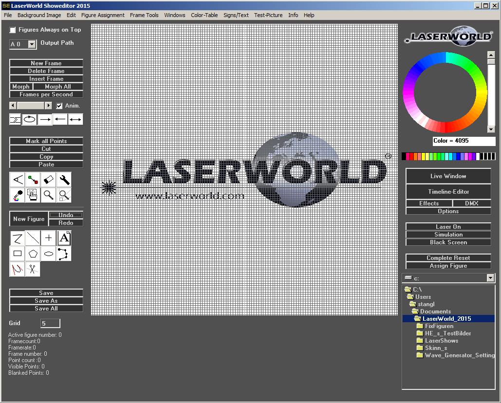
Fig.61: Figure Editor: Background image
6.14.4. Hidden Background Image
The background image can be hidden by activating this menu item
6.14.5. Edit Laser Frame / Edit Background Image
There is the option to either edit the laser frame or the background image. Selecting one of the options unselects the other one.
Editing the background image allows for changing the image with using the drawing tools – it only changes the image, not the drawn laser figure. Selecting “Edit Laser Frame” allows for directly drawing lines and vectors for the actual laser output. This is the standard setting and needed in most cases.
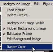
6.14.6. Raster-framing: The Raster Color Tool
Raster-framing is the projection of “real” images with laser – not only the outlines, but also filled areas. As this method of image projection is very demanding for the scanners, it is highly suggested to be very careful when creating and displaying raster frames.
The Laserworld Showeditor has an automatic raster frame conversion tool built-in – it’s called “Raster Color”.
The tools works in 3 steps:
- Select the image to be displayed
Click on Background Image -> Load Image to load the desired image as background of the drawing area. The part of the image that should actually be converted to a raster frame can be selected in the next steps.
- Define the grid size
It’s very essential to properly define the grid size before continuing with the raster frame process. This is important as the grid size specifies the number of points that are drawn during the conversion. The more point are drawn, the harder it is for the scanners to actually display the figure. Grid sizes from 8 to 10 usually give good results.
- Specify the area of the background image that shall be rastered
Drag a selection square around the parts of the background image that shall be rastered. Use the Hand tool for doing so (with left click and drag):
- Select the “Raster Color” tool
- Specify the raster type
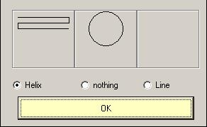
The standard selection is “Helix”, but especially for circular objects “nothing” can be an option too.
When having followed all the steps above, the raster frame is generated automatically by creating the corresponding points in the respective color in the density specified with the Grid size before.
Important:
It is very hard for scanners to project raster frames, as the requirements are really high. Si it is recommended to project raster frames as small as possible and better mount the laser in a bigger distance to the projection surface. This makes it easier for the scanners to handle the high point density, as the inertia doesn’t affect the scanning in small angles too much.
As raster frames are so difficult to handle for scanners, they are very likely to flickering if the scan speed is too low. This is a normal behaviour. To reduce flickering, either use a bigger grid size to reduce the number of points, or use a faster scanning system. Reducing the size of the projection can also help with significantly reducing the flicker effect.