
")
6.3. Marking- and Editing-Tools
6.3. Marking- and Editing-Tools
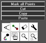
New or already existing figures can be edited. A set of different marking- and editing-tools are implemented in Laserworld Showeditor (Fig.39).
6.3.1. Hand:
 The hand-tool is the most important tool for creating figures. With this tool points of a figure can be marked. To mark points, select the tool and left-click and drag a selection square
in the drawing area, so all points in the desired region become selected.(Fig.40).
The hand-tool is the most important tool for creating figures. With this tool points of a figure can be marked. To mark points, select the tool and left-click and drag a selection square
in the drawing area, so all points in the desired region become selected.(Fig.40).
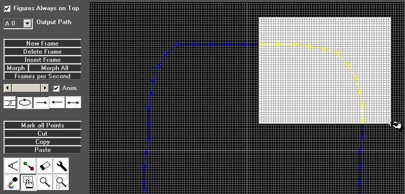
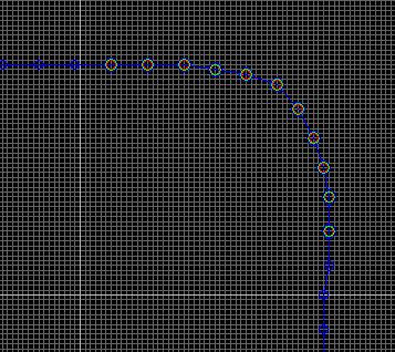

Fig.40: Figure Editor: Tool “Hand”. Point selection by left-click and dragging of selection square. The marked points are indicated by coloured circles: The hand-tool gets a red background to indicate that a region is marked.
Sometimes it may be necessary to set the grid to 1 to be able to select points which are not easily accessible as lying in another layer.
If the hand tool gets a red background, this indicates that there are already one or more points marked. (see Fig.40) The marked points get a colored circle.
Additional points can be marked by holding the “Ctrl”-key. To mark ALL points use the appropriate button “Mark all points”.
Marked points can be moved by using the right mouse button: right-click, hold and drag.
If no specific point is marked yet, the point under the mouse pointer can be moved with right-click, hold and drag – this obviously only moves one point.
6.3.2. Cut/Copy/Paste:
 The Cut / Copy /Paste buttons simply do what would be expected. Pasted points are automatically marked and can be moved immediately
with using the hand tool. If points are pasted to the same frame, make sure to drag the marked points away before unselecting them, as otherwise the points overlap. This usually is no problem if points are pasted to another frame of course.
The Cut / Copy /Paste buttons simply do what would be expected. Pasted points are automatically marked and can be moved immediately
with using the hand tool. If points are pasted to the same frame, make sure to drag the marked points away before unselecting them, as otherwise the points overlap. This usually is no problem if points are pasted to another frame of course.
To copy or cut and paste a series of frames, use the menu item Frame-Tools (see chapter 6.18 for further information on the Frame Tools).
Cut or copied points or frames can be pasted into other figures and frames, too. This can be very helpful if animated figures shall be created.
The commonly known shortcuts “Ctrl” + C for Copy, “Ctrl”+ X for cut and “Ctrl” + V for paste work as well.
6.3.3. Rotation Tool:
 The rotation tool allows for rotating marked points. The rotation-center is the position where the mouse button is clicked within the drawing area. A horizontal movement with
clicked mouse button results in a rotation with angle zero. A movement down means a +90 degree rotation, a movement up means -90 degree rotation etc. The rotation will be applied on release of the mouse button.
The rotation tool allows for rotating marked points. The rotation-center is the position where the mouse button is clicked within the drawing area. A horizontal movement with
clicked mouse button results in a rotation with angle zero. A movement down means a +90 degree rotation, a movement up means -90 degree rotation etc. The rotation will be applied on release of the mouse button.
6.3.4. Change-Color Tool:
 The color of points and corresponding lines can be custom changes, also after drawing. The Change-Color Tool can be used for recoloring existing points. To apply a color
change, first mark the points to be changed. Then select the desired new color from the color circle, cube or palette and finish the re-coloring with a click on the Change-Color tool button.
The color of points and corresponding lines can be custom changes, also after drawing. The Change-Color Tool can be used for recoloring existing points. To apply a color
change, first mark the points to be changed. Then select the desired new color from the color circle, cube or palette and finish the re-coloring with a click on the Change-Color tool button.
This procedure works for single points as well as for several points with connecting lines.
If there are no points marked and the tool is selected, the color of the point just under the mouse cursor is changed. Besides that it is possible to hold
the mouse button and change the color of all points that are hit by the cursor by dragging the mouse.
By using the left mouse button for the re-coloring procedure, only visible points are changed. Use the right mouse button to recolor blanked (invisible) points.
To work on blanked points, they should be made visible
in the in the drawing area by setting Edit -> Blanked Lines Visible. If an endpoint has been made visible with any of the procedures above, a dialog shows up asking if a blank point shall be inserted.
6.3.5. Erase Tool (Delete):
 Marked points can be deleted with this tool. If no points are marked, the point under the mouse cursor is deleted. By clicking and dragging the mouse, all points hit by the cursor
will be erased.
Marked points can be deleted with this tool. If no points are marked, the point under the mouse cursor is deleted. By clicking and dragging the mouse, all points hit by the cursor
will be erased.
6.3.6. Wrench Tool (Optimize Output):
 The point and line output behavior can be controlled with the wrench tool. A click on the icon opens a dialog that offers different options for selection (Fig.41):
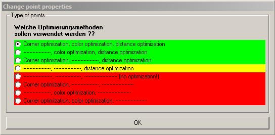
Fig.41: Wrench Tool: Point Optimization
There are different ways of optimizing the points of a frame for proper output. Each point has specific “properties” which especially mean their relation to other points.
Three main optimization methods and their combinations can be
selected.
Please remember, that some optimization methods may destroy your Galvo scanner system! These methods are marked with a red background color. The methods with green and yellow background should not harm normal Galvo scanner system (depending
on properly set scan-rate).
Properties of points – explanation:
A rectangle consists of 4 corner points and the lines between them. A Galvo scanner system is, without optimization, not able to simply project these 4 coordinates, because of its resonances
and its physically given inertia (mainly of the mirrors that need to move very very fast. The bigger and heavier the mirrors are, the higher is the inertia). Too slow Galvo scanners are not able to display the corners correctly. The rectangle then becomes
something like a circle. Too fast Galvo scanners fast mainly display the corner points, but the lines are missing or too less intense. Thus it is necessary to optimize the ways of movement for each Galvo system. The optimization “interpolates”
the 4 lines between the corners – which means that the lines are virtually split to small pieces. The corner points are repeated several times for an intense and precise projection. The number of small line peaches necessary and of the corner repetitions
depends on the Galvo scanner system.
For these kind of optimizations the term “properties of points” applies: line points have other properties than corner points. Each element (circle, square, letters etc.) has its own properties.
In order for Laserworld Showeditor to understanding how to work with the respective points and lines, each point has certain properties. These properties define how to optimize the output for the very Galvo scanner system.
6.3.7. Pipette (copy color):
 If colors of one point shall be used for another point, the Pipette tool is used. First select the desired points where the color should be picked up, and then click on the pipette
tool icon. By selecting other points of the figure, they get the same color as the original point(s).
If colors of one point shall be used for another point, the Pipette tool is used. First select the desired points where the color should be picked up, and then click on the pipette
tool icon. By selecting other points of the figure, they get the same color as the original point(s).
6.3.8. Magnifying Glass:
 The magnifying glass tool is used for zooming-in to the drawing area. This allows for much more detailed work, as it can zoom down to the very pixel.
Hint:
If the Grid size is set to 0, the frames can be drawn exact by pixel.
There are several ways for using the magnifying glass:
A) Select the magnifying glass and select an area with clicked left mouse button. The selected area is displayed magnified. The marked region is stretched to fit the drawing
area. Thus distortions may occur.
B) Select the magnifying glass and move the mouse cursor to the point where the magnification is needed. Use the mouse wheel for zooming.
When a zoom is set, the frame can be reset to normal 100% view by left-clicking on the magnifying glass icon again. With a right click on the icon, it is just re-selected and the click does not affect the current zoom level.