
")
8.8. Tab “Optimize Output”
8.8. Tab “Optimize Output”
The settings in this tab influence on the output performance and –quality. Carefully read the descriptions, as wrong settings can destroy the scanners of the laser system.
Output Optimization is essential for graphics and projection shows, but is recommended for any kind of show.
As every scanner system has different behaviour (depending on the quality of the motors, the size and the weight of the mirrors as well as the driver electronics), so is the modulation behaviour of the laser sources. Thus it is difficult to provide “standard” settings. However, the output should be acceptable with standard settings for most laser projectors.
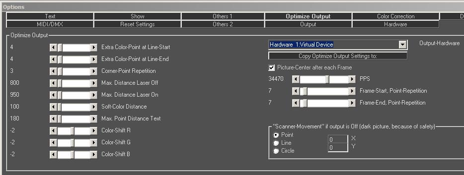
Fig.94: Options Window, Tab “Optimize Output”
These parameters apply to any output optimization changes:
- The optimization of the laser output is in real-time, meaning the changes are directly put out to the laser system (if connected) and can be seen live.
- Each hardware output channel must be optimized individually.
- Color correction options may also be affected by optimization measures. These can be found in the tab “Color Correction”
A tutorial on how to configure scanners to optimal output performance can be found on: http://www.showeditor.com/tune-scanners
Information: The test pictures (with file extension *.bin) are nearly NOT optimized. The pictures from the folder “HE-s_Testbilder” are optimized, as they are “normal” Showeditor figures.
Remember that Laserworld (Switzerland) AG is not responsible, nor liable for the correct control of the laser projector. Please refer to the disclaimer for further details.
8.8.1. Extra Color Point at Line Start
This specifies the number of additional points that are added at the beginning of a line on a color change (NEW color). It applies to the transition blanked->Laser On setting, as well as on a change between colors.
8.8.2. Extra Color Point at Line End
This specifies the number of additional points that are added at the end of a line, before another line piece / object is drawn with a different color. It applies to the transition blanked->Laser On setting, as well as on a change between colors.
8.8.3. Corner Point Repetition
This setting specifies how often a point is repeated, if its property is defined as corner point. More repetitions will result in sharper, but also brighter edges. Corner points are usually defined automatically on the creation of figures.
Polygons, rectangles, line start and line end are corner points. Circles have NO corner points, as well as waves have none. Depending on the setup, this setting applies to freehand drawings, too. The properties of points can be changed manually using the “wrench tool” (see chapter 6.3.6.).
The value set as corner point repetition specifies the MINIMUM NUMBER OF REPETITIONS of corner points. If a corner point has already been repeated several times by the color correction, the Corner Point Repetition only adds the difference.
8.8.4. Max. Distance Laser OFF
The Max. Distance Laser Off setting specifies the maximum length of the path the Galvo moves with laser output off (blanked). Galvos are not able to move freely in blanked mode over longer distances without this interpolation, therefore this setting is important. Typical values are between 500 and 2000. Depending on the point properties, the settings here may not have any effect under certain circumstances. If the distance of points of a blanked path is longer than the specified value, the line is automatically split and additional blanked points are inserted.
8.8.5. Max. Distance Laser ON
The Max. Distance Laser ON setting specifies the maximum length of the path the Galvo moves with laser output. The behaviour and application is the same as for “Max. Distance Laser OFF”.
8.8.6. Soft Color Distance
If “Soft Color” is activated in the Effects Dialog, the value specified for Soft Color Distance defines the distance between the points for color transitions.
The colors between two colored points get a smooth transition from one color to the other one. Shorter distances make the color transition look nicer and smoother. In most cases a value of 500 is a good choice. If Soft Color is selected, no extra color points are set on line start and line end. Slower Galvos may require a higher value, so do laser systems with laser sources that have slow color modulation.
8.8.7. Max. Point Distance Text
The settings for Max. Point Distance Text have the same behaviour as the ones for “Max. Distance Laser ON/OFF” except that they apply for letter / text projections only.
8.8.8. Color Shift R / G / B
The three scrollbars “Color Shift” control if the laser sources shall be switched on slightly before or after the actual point is drawn. The reason is that the laser sources usually respond faster than the Galvos do (only in very rare cases the laser sources have a slower modulation). This difference in response speed can be corrected by setting the appropriate values.
With using this optimization, the settings for “Frame Start, Point Repetition” and “Frame End, Point Repetition” are changed as well. This is required, as the software needs enough extra points for shifting the colors accordingly.
Further details on color shift optimization can be found at:
http://www.showeditor.com/color-shift
8.8.9. Output Hardware
As any output optimization setting applies per hardware, the desired output channel must be specified. This is done with the Hardware Output dropdown menu.
Any settings refer to the hardware NUMBER, which can be selected here – not to the physical DAC (which can be the same, but doesn’t need to be).
This means that changing the physical interface (DAC) for Hardware 1, the optimization parameters are preserved and are used with the newly applied DAC.
8.8.10. Scrollbar PPS
The PPS scrollbar specifies the actual output scan speed for the selected hardware device. The “PPS” is an acronym for Points Per Second ad specifies the output rate of the scanners. This setting must be adjusted to match the scanner system of the laser projector.
For determining the correct PPS rate for the very scanner system, please refer to our tutorial: http://www.showeditor.com/tune-scanners
8.8.11. Picture Center after each Frame
If this option is selected, the Galvo mirrors always move from the picture center to the first point of the figure and from the last point back to the center. This setting is required for some Galvo. It is better to select the option if its requirement is unclear. “Wide Move Scanners” work with this option unchecked.
Basic Galvo systems require this option checked. The movement to the centre adds about 20 additional points, but it makes sure that longer movement paths are displayed correctly.
8.8.12. Frame-Start, Point-Repetition
The additional blanked points that are additionally placed at the initial projection point of the figure are specified here. The number automatically increases, if the value for the Color Correction is negative. The value can not be smaller than the number of color shift points. Usually this value has no significant effect on modern show laser light systems, so the smallest possible value can be chosen.
8.8.13. Frame-End, Point-Repetition
The additional blanked points that are additionally placed at the last projection point of the figure are specified here. The number automatically increases, if the value for the Color Correction is positive. The value can not be smaller than the number of color shift points. Usually this value has no significant effect on modern show laser light systems, so the smallest possible value can be chosen.
8.8.14. Scanner movement, if output is off
These settings specify the scanner behaviour under two different circumstances:
- Scanner Safety is in use
If the laser projector is equipped with a scanner safety, delays if the laser output can happen after blacked out sequences. Different types of safeties are available. If a type is in use that monitors the scanner movement only, it can happen that the safety jumps in even if there is just a small break in the show and, depending on the laser model, a mechanical shutter snaps into the beam path. This behaviour is safety related, but in most cases unwanted during a show, as there is quite some delay for the lasers to come on again after such an interruption.
- Suppression of Stand-by beams during a show
Depending on the laser system and it’s configuration a very dim laser “blind beam” can be visible if the scanners are not moving. By using the Scanner Movement feature it is possible to “suppress” the blind beam output, as the scanner movement makes it invisible.
To avoid these behaviors, it is possible to have the scanners make a circle or line movement if they experience a stand-by time during the show. With specifying the X and Y offset, the position of the “blanked movement” can be defined. “R” can be used for setting the radius for a circle, X2 and Y2 are used for specifying a line size. Allowed values are in the range of +- 32767 (only positive values for circles)