
")
2.5. Laser Output Hardware (DAC)
2.5. Laser Output Hardware (DAC)
Laserworld strongly recommends to only using the ShowNET interfaces with Laserworld Showeditor. The software is optimized for this DAC, and the licensing is also handled through it.
The interfaces (DAC) can be selected at Options → Hardware. In the drop down lists the connected interfaces can be selected. For special applications it is possible to select the same interface in two lists (matrix-match). This is especially useful, if two different settings (e.g. output options) will be applied. Output should only be made to one of the selected lists per interface, as otherwise the signals overlay and may lead to flickering output.
An example for such an application would be a mixed show with graphics and beams: For the graphics display, the output is set to fit to a screen, for the beams a setting with different parameters is chosen.
Another possible application could be the use of a playlist containing a mixture of different show types (e.g. graphics, 1 projector beam, 3 projector beam, 1+2 projector beam etc.). This kind of use is explained in the chapter “Playlist”.
The different hardware interfaces can be custom named, to make them easier to identify. (e.g. “Main Projector”, “Satellite 1”, “Graphics Projector”…).
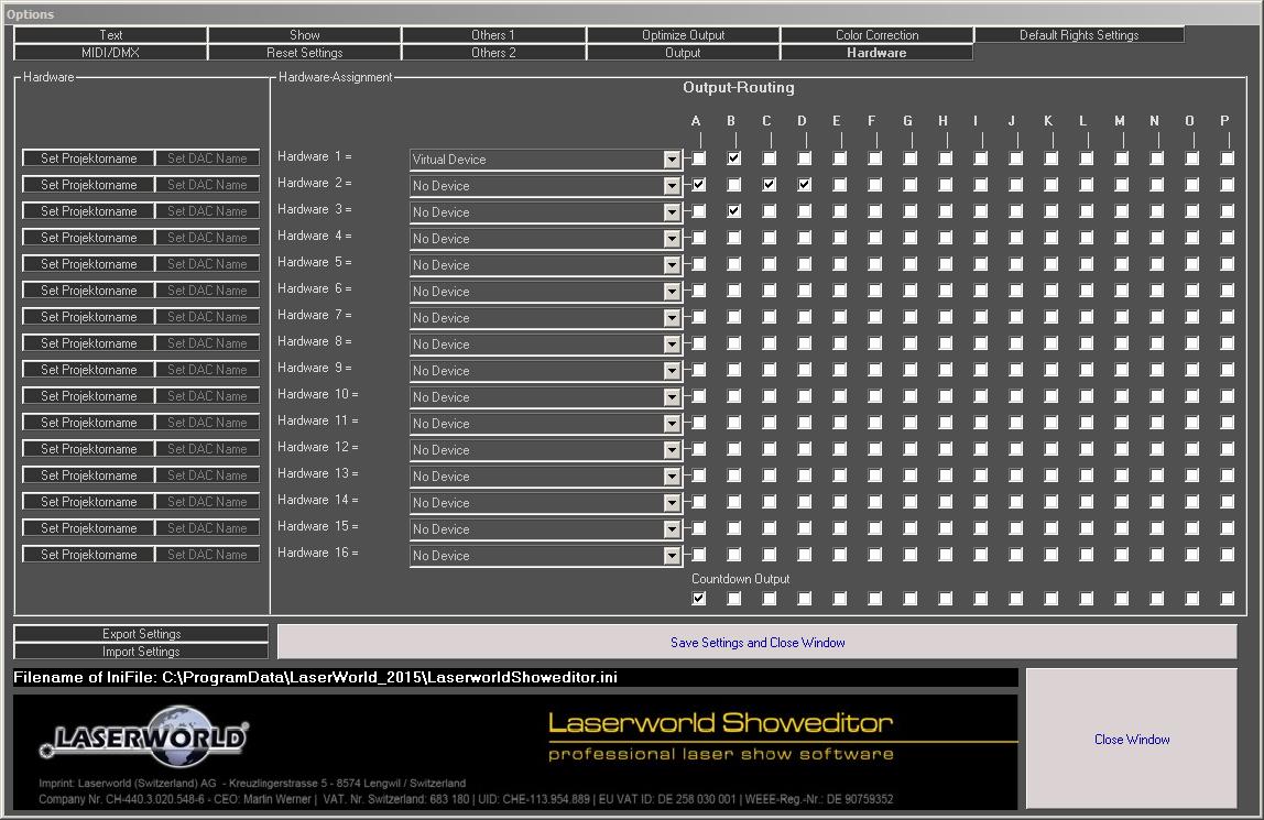
Fig.2: Menu “Options/Hardware” for the selection of the hardware interfaces (DAC). Up to 16 interfaces can be used. The shown setup is useful for a simulation of a 1 + 2 projector show (typical setup).
2.5.1. Simulation and Virtual Device
For a simulation/visualization of the laser show, no real output hardware device is required. But it is essential, that the “Virtual Device” is assigned to the respective output channels in “Options -> Hardware”. If there is no real hardware device detected, at least one “Virtual Device” is selected as standard.
If the software detects any DAC, it will be automatically added to the list in the order they are detected. The automatically assigned positions can of course be changed according to user requirements.
Independent of the type of connected “hardware”, the simulation can be started by opening the respective window (see Fig.9). In case only virtual devices are connected, the simulation window is opened automatically when clicking on “Laser ON”.
The simulation of course also works with real hardware interfaces connected, however only visualization or real laser output can run – they cannot both be run at the same time.
To start the simulation, click on the “Simulation” button. A window opens that displays the actually selected figure(s).
The window title bar shows the number of points currently shown. This can help to flicker-optimize the output of the laser projector(s) used.
The simulation must be started prior to starting the show. The simulation window will automatically be attached to the top layer and thus stays in the foreground.
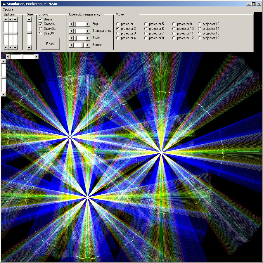
Fig.3: Simulation of figures and laser-shows. Use right mouse button to open the setup dialog (above).
The simulation uses Direct-X 8.0 (or newer) or OpenGL. With Direct-X, the simulation works quicker, but is not as accurate. It is possible to simulate beam shows as well as graphics shows. Also a combination of beam and graphic is possible (like used in Fig.5).
Up to sixteen simulated projectors are possible. To open the dialog to adjust the simulation, click the right mouse button in the simulation window or use the menu “Options”. A second right mouse button click will close the dialog. A click and hold on the center position of the selected projector allows to move it’s position. The selection of a projector is done with the radio buttons on the right side of the dialog. On closing the window, the settings are stored to the *.ini-file.
The Fig.4 shows an example for a simulation setup with 1 plus 2x2 projectors (one main projector and two satellite pairs).
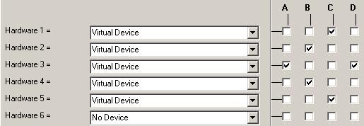
Fig.4: Simulation with virtual devices.
Hint: It is also possible to start Laserworld Showeditor by double-click on a Showeditor *.ini file. So it may make sense to create a separate *.ini file for the settings of the simulation (virtual devices, positions of projectors, movements, etc.) and to export these settings to e.g. “simulation.ini”. This way several *.ini files could be saved with different simulation settings. Simulations with the respective settings then can simply be started with a double click on the corresponding *.ini file.
Troubleshooting – Simulation is not working or not displaying correctly:
- If the simulation is displayed incorrectly or distorted, a click on the reset button may fix the display error.
- After a new installation of the software, the parameters for the simulation display may not 100% fit the requirements. Please use the reset button to fix this issue.
- If the color correction setup for the hardware is not done correctly or missing at all, the simulation can not visualize properly.
- The drivers for the graphics board need to be installed correctly. The simulation requires the OpenGL engine.
- During the laser show simulation, a laser output through DACs is not possible: The output is redirected to the simulation – including output parameters like x-axis mirroring or output size.
To end the simulation, just click on the cross in the upper right corner of the window. If you click on “Laser Off” (or you stop the show), the simulation window disappears, but will automatically reappear on restart of the output.
2.5.2. Friendly Names
Each DAC interface can be named individually. The name can be set in the hardware options (Options -> Hardware) with click on the button “Set Device Name”. This “Friendly Name” is stored on the DAC, so it shows when connecting it to a different computer too.
2.5.3. MIDI / DMX (Hardware and Driver)
The setup of the MIDI and DMX-hardware is done in the dialog Options->MIDI/DMX (Fig.5)
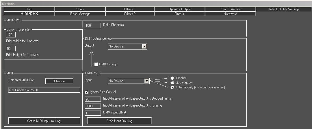
Fig.5: Menu Options/MIDI/DMX: Selection of DMX-ports for input and output, selection of MIDI-device and setup of printer.
Different output interfaces can be assigned for DMX input and DMX output. The duration of the request-interval for the input can be adjusted (dependent on the laser output).
2.5.4. DMX Settings
Laserworld Showeditor supports DMX input as well as DMX output. With DMX in it is possible to remote-control most features of the software with a DMX controller (or a DMX software). This is especially useful in Live-Mode, as real faders could be used for controlling the effects, brightness and speed assigned to the patterns.
DMX out can be used for controlling DMX fixtures of any type, e.g. moving lights, pyrotechnical effects or fog machines.
For using the DMX features of the ShowNET interface, it is necessary to connect the DMX-Adapter to the ILDA line. The DMX Adapter can be purchased through Laserworld or their distribution partners.
2.5.5. MIDI Settings
Each installed MIDI-port on the PC should be automatically recognized by Laserworld Showeditor, including virtual ones. MIDI can be used to control the Live Window, the Timeline as well as the playlist. It is especially useful for recording a show in the timeline window, e.g. can figures be assigned by “playing” on a MIDI keyboard.
MIDI ports must be assigned manually before they can be used. Laserworld offers several MIDI presets for a selection of MIDI devices; those configurations can be downloaded in the download section on http://www.showeditor.com
A MIDI-port can be selected at Options->MIDI-DMX-Printer (Fig.5), then “Change”. A dialog for selecting the desired MIDI-port opens. Only the MIDI-IN-port is used! In many cases the MIDI routing must be adapted to the very device in use.