
")
8.10. Tab “Color Correction”
8.10. Tab “Color Correction”
The Color Correction is used for specifying the power levels per laser source color channel. This Tab also provides the options to set safety zones (beam attenuation map) and control the color handling behaviour.
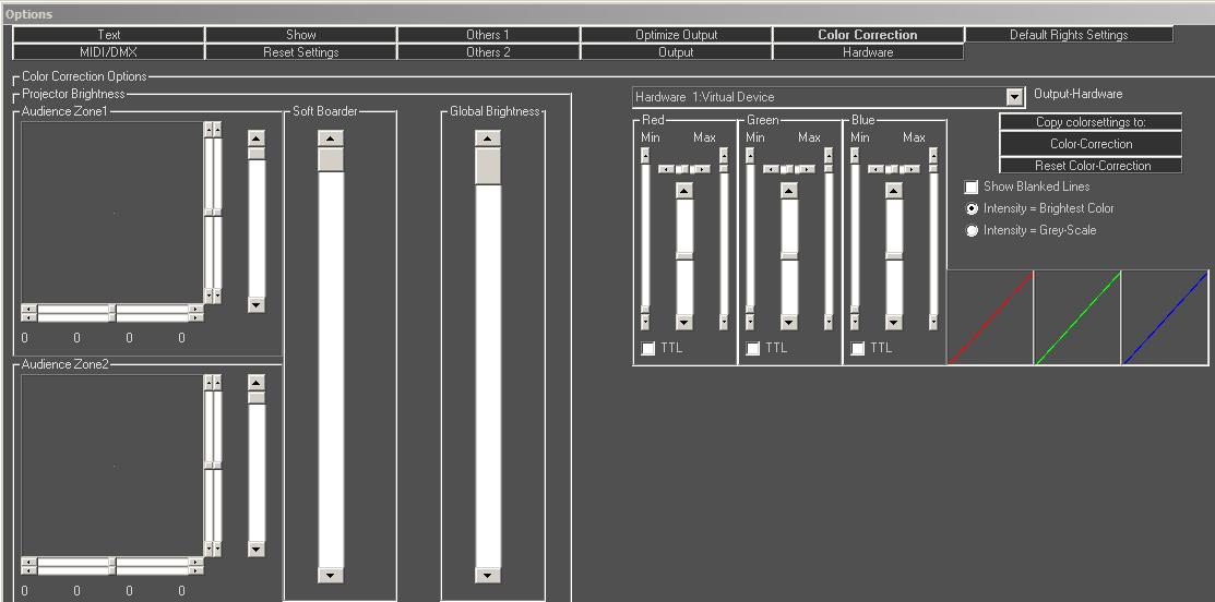
Fig.96: Options Window, Tab “Color Correction”
8.10.1. Show Blanked Lines
This option is a help for setting up the correct values. If checked, even the invisible movement paths of the beam are made visible. To distinguish them from “normal” lines (un-blanked), they are colored RGB in small bits. (single color lasers show colored-black lines).
Attention! If a figure consists of zero points (actually no figure), a single beam is projected! A warning message is displayed in this case.
8.10.2. Intensity = Brightest Color / Intensity = Grey-Scale
There are two options how the intensity of color output can be calculated, which can be selected here. Changing the standard setting (Brightest Color) only makes sense for applications where the intensity signal of the DAC is used. Grey-Scale leads to overall less bright output color, however this option may be required under certain circumstances.
8.10.3. Button Color-Correction
The click on this button opens the Color Correction dialog shown in Fig.98.
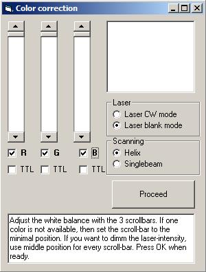
The color correction dialog provides another method for the basic color correction setup. One main feature, however, is the possibility to make the color adjustments when running the laser sources in cw mode (full power).
This dialog was used in former times for the colour correction and today it is not really necessary any more. Nevertheless it can be used to make a pre-setup of the colour correction anymore. When having made a selection, the info area at the bottom provides further details. Follow the instructions given in the info area.
Select either “Laser CW mode” to compare the laser color balance and brightness of the lasers in full power mode or select “Laser blank mode” to compare color balance and brightness in normal modulation mode. For configuring the white balancing for a laser show, use the “Laser blank mode” in combination with Helix scanning.
In case the laser projector is not equipped with R-G-B laser sources but only with one or two colors, the corresponding checkbox of the very color shall remain unchecked, so the control signal that comes in for the missing color is distributed to the existing color(s).
On clicking “Proceed”, the selections made are passed to the general color correction tab and the Color correction dialog closes.
8.10.4. Extended Color Correction (Min/Max scroll-bars for RGB)
Fig.98 shows the extended color correction:
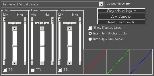
Fig.98: Options Window, Extended Color Correction
Each color channel can be individually adjusted: The extended color correction allows for configuring a non-linear dimming behaviour per color channel. This feature can also be used to force the color brightness to a certain smaller range which can increase brightness (but negatively impacts on the fading behaviour).
The Min scrollbars specify the minimum modulation voltage for the laser source, meaning the voltage where the laser source starts with it’s minimal output power (threshold). Set this scrollbar just slightly below this threshold to be able to blackout the laser source. Properly configuring the threshold helps the laser sources with reacting to control signals more quickly.
The Max scrollbars specify the maximum modulation voltage for the laser source. This setting limits the maximum brightness of the color channel.
The scrollbars in between work similar to those of the “parametric middle” in a sound mixer. The horizontal scrollbars determine the position of the on and off of an interpolation point. Use these scrollbars in between to set a nonlinear response curve.
TTL lasers: If a laser source can only modulate in TTL (on/off), the TTL-box must be checked. This results in all brightness values being put out with full intensity.
8.10.5. Area “Projektor Brightness” – Safety Zones, Beam Attenuation
“Audience Zone”: Two Safety Zones can be specified in Laserworld Showeditor: These are areas where the laser output power is reduced. This feature is usually used to reduce the output power in the close audience are to stay within the MPE although the laser itself has more power. Overhead beams usually don’t require further power reduction (see your local laser regulations!) so the safety zone is a good way of only reducing a part of the laser output and maintain the ability to shoot aerial effects with full power.
It is suggested to project a grid test pattern when setting up the safety zones to be able to immediately see the results of any adjustments.
“Soft Border”: The soft border setting controls the behaviour of border softening / fading for the projections.
“Global Brightness”: This allows for setting the global brightness for the laser, affecting all color sources to the same extent. Settings in the Safety Zones always refer to this setting, so if the global brightness is reduced, this also reduces the relative power reduction for the safety zones.