2.8. Initial Settings
2.8. Initial Settings
On first start of Laserworld Showeditor it is suggested to adapt the Settings to the very needs: Language, hardware, output behaviour and many more features can be defined there.
Usually any supported hardware interface that is connected to the computer is automatically detected by the Showeditor software. To make sure everything is connected and assigned correctly, please verify the settings.
Important information on Settings and their effect:
Changes to any parameter have immediate effect. To preserve the settings even after a restart of Showeditor, a click on “Save Settings and Close Window” writes them to the startup configuration file.
2.8.1. Setting “Others”:
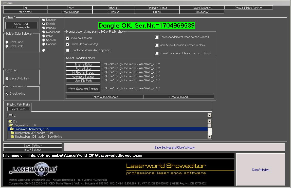
Settings can be accessed in the Options menu, then change to the tab Others. If you require to changing the interface language of Laserworld Showeditor, this can be done here (e.g. English, see Fig.8).
If a correctly licensed ShowNET interface is detected, the corresponding serial number of this interface is shown here.

Fig.8: Menu: Options. Language selection, licensing information
In the lower part of this settings tab the standard paths of Showeditor are defined. The standard settings are fine in most cases.
2.8.2. Setting “Hardware”:
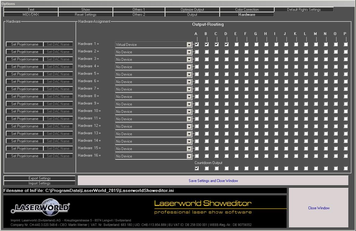
Change to the tab Hardware. Hardware devices are detected automatically, but can be custom assigned per channel in this tab.
Up to 16 Digital-Analogue-Converters are supported by the software, so the very hardware device can be routed to the respective output channels.
It is also possible to assign a “Virtual Device” to the hardware channels. This is required if no real hardware output interface is connected to the computer or if more than the connected hardware interfaces shall be used for programming and 3D preview.
If Laserworld Showeditor is run in Freeware/Demo Mode, only one hardware channel can be assigned and only the virtual device can be chosen.
The Output Routing describes which hardware interface should output which programmed track, so it’s also possible to route several tracks to one hardware interface or vice versa.

Fig.9: Options: Hardware Output Routing
2.8.3. Optimize Output
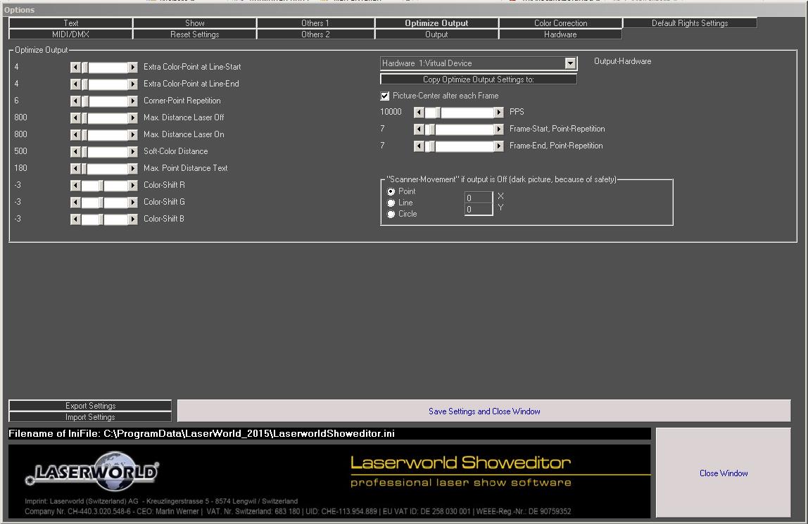
The tab Optimize Output allows for configuring the output settings of the very hardware output device. These settings are important as they impact the output quality. Settings that do not fit the scanners used in the very laser projector may lead to damage of these scanners, so always read the user manual of the show laser system you’re using at the respective hardware interface first!
Most important is to set the PPS-rate (PPS is an acronym for points per second) for the respective Galvo system/scanner-system used in the laser system that is controlled with the very hardware interface.
To get started it is recommended to set this value to 2/3 of the maximum given PPS rate of the Galvo system/scanner system (see user manual of the show laser system).
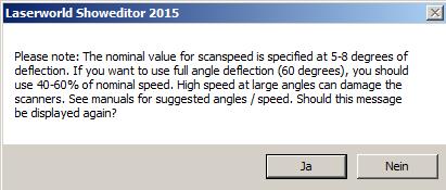
Setting the scan rate too high may damage the scanners, so extra care needs to be taken when setting this. If scan speed settings of more than 25’000pps are selected, a warning message shows up, explaining that this may damage scanners if not used with precaution. You can stop this dialog box from opening up again by clicking “No” (“Nein”):

INFOBOX:
It is strongly recommended to not daisy-chain an ILDA signal line to connect laser systems with different scanner systems. Either the slower scanner system is overdriven when optimizing settings to the faster one, or the faster one can only run at the speed of the slower one when settings are optimized for this. Use two different hardware interfaces instead and set the scanner settings per interface.

Fig.10: Tab Optimize Output. Setting of hardware interface parameters
After having set the scan speed, different adaption to the general scanner behaviour can be made. It is suggested to project a test pattern while adjusting these fine tuning settings: The left column of faders in this Tab is especially suited for fine tuning of the output. It is recommended to follow the “Scanner Optimization” guide when applying settings here. See chapter Tab “Optimize Output for details.
A reset of each fader position can be done by double-clicking on the explanatory text next to it.
2.8.4. Save your settings
Changes to any parameter have immediate effect. To preserve the settings even after a restart of Showeditor, a click on “Save Settings and Close Window” writes them to the startup configuration file.


